
Service
Soil Nailing
Top-down in-situ reinforcement of cuts, slopes and deep excavations using grouted steel nails and shotcrete facing.
Overview
Soil nailing that holds the ground exactly where you cut it
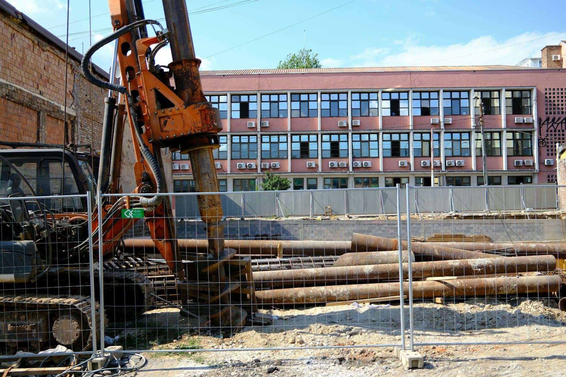
Soil nailing reinforces existing ground in place. Closely spaced steel bars are drilled and grouted into the face of a slope or excavation as it is cut from the top down, and a reinforced shotcrete skin ties the nail heads together. The nailed soil behaves like a coherent gravity block that supports itself.
Because it needs no space in front of the wall and uses compact drilling rigs, soil nailing is often the only practical way to retain a cut next to existing roads, buildings or steep hillsides — and it is usually faster and cheaper than anchored walls or secant piles in suitable ground.
Typical soil nail wall cross-section
- Reinforced shotcrete facing
- Grouted steel nail, inclined 10° – 20° downward
- Bearing plate and nut at the nail head
- Potential failure surface (nails cross it)
- Geocomposite drainage strip and weep holes
- Excavation lifts, 1 – 1.5 m, nailed top-down
Schematic only — not to scale. Final design is project specific.
Benefits
Why choose soil nailing
Works in tight sites
Light rigs operate from the bench being cut, with no need for large piling plant or working space beyond the excavation line.
Top-down and quick
Each lift is excavated, nailed and faced before going deeper, so the face is never left unsupported for long.
Adaptable to the ground
Nail length and spacing can be adjusted as the real ground is exposed, which suits variable soils and weathered rock.
Lower cost than anchors or piles
Passive nails need no stressing equipment and use less steel and concrete than a retaining system built in front of the ground.
Temporary or permanent
With the right corrosion protection and facing, nailed walls are used as permanent works as well as temporary excavation support.
Verified by testing
Pull-out tests on sacrificial and production nails prove the design bond strength before the wall relies on it.
Execution
Our soil nailing sequence
- 1
Investigation and design
Soil profile, groundwater and nearby structures are reviewed. Nail length, inclination, spacing and facing are designed and checked for global stability.
- 2
Excavation in stages
Excavate a 1 – 1.5 m lift (limited by how long the ground will stand unsupported) and trim the face to the design profile.
- 3
Drilling
Holes of 100 – 150 mm diameter are drilled at a slight downward angle, usually 10° – 20°, using rotary or percussive drilling; casing is used where the hole collapses.
- 4
Nail installation
High-yield deformed steel bars (typically Fe 500D) are fitted with centralisers, and corrosion protection appropriate to the design life.
- 5
Grouting
Cement grout is pumped from the bottom of the hole until it returns clean at the collar. Grout cubes are taken to confirm strength.
- 6
Drainage and facing
Geocomposite drainage strips and weep holes relieve water pressure. Mesh is fixed and 100 – 150 mm of shotcrete applied, with bearing plates and nuts at each nail head.
- 7
Repeat, test and monitor
The cycle repeats to full depth. Pull-out tests are done on trial nails, and survey targets or inclinometers track wall movement during and after construction.
Specifications
Typical parameters
| Nail | HYSD bar Fe 500D, 25 – 32 mm diameter |
|---|---|
| Drill hole | 100 – 150 mm diameter, 10° – 20° below horizontal |
| Nail spacing | 1.0 – 2.0 m grid, closer near the top and in weak ground |
| Nail length | Commonly 0.6 – 1.0 × excavation height |
| Facing | 100 – 150 mm shotcrete with welded wire mesh and bearing plates |
| Excavation lift | 1.0 – 1.5 m, depending on stand-up time of the ground |
Values are indicative. Final parameters are set by the project design and specification.
References
Standards & guidelines
- FHWA-NHI-14-007 (GEC 7) — Soil nail walls
- IS 456 — Plain and reinforced concrete (shotcrete and grout strength)
- IS 2720 — Methods of test for soils
- Project-specific geotechnical design basis and owner's specification
FAQ
Soil Nailing: your questions answered
Read more
Related guides
Also from Terrabindz
Related services
 01
Reinforced Earth Walls
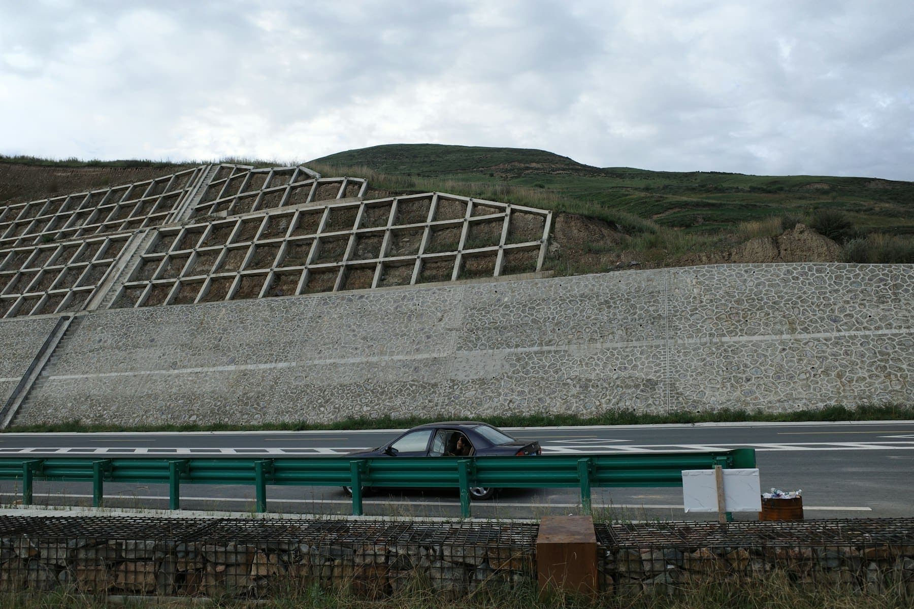
Precast-faced MSE walls and reinforced soil slopes for bridge approaches, flyovers, highways and industrial platforms.
Explore service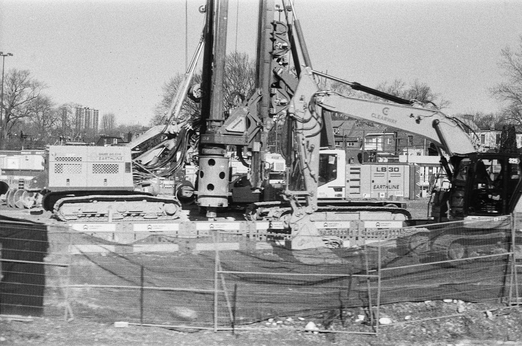 03
Ground Improvement
Stone columns, dynamic compaction, preloading with vertical drains and stabilisation for soft, loose and expansive soils.
Explore service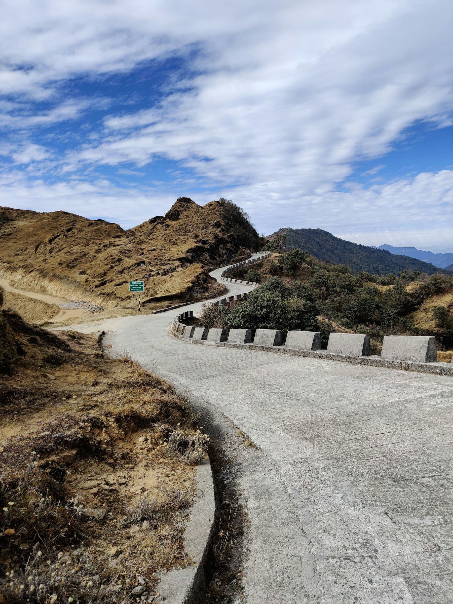 04
Slope Stabilisation
Rock bolting, shotcrete, wire-mesh rockfall protection, gabions, geogrid slopes and drainage for cut and natural slopes.
Explore service
Free consultation
Have a project in mind? Let's talk ground conditions.
Share your drawings or soil report and our engineers will respond with an approach, programme and quotation.